Concept projects. These are concept studies developed by the studio to show its method: they are not manufactured products or work done for a client. Client work stays confidential.
- Food-grade stainless steel tank, 1,000 L on skid
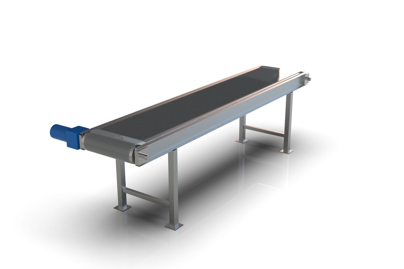
- Belt conveyor, 3 m × 500 mm, slider bed
- IP65 aluminium enclosure with a finned lid
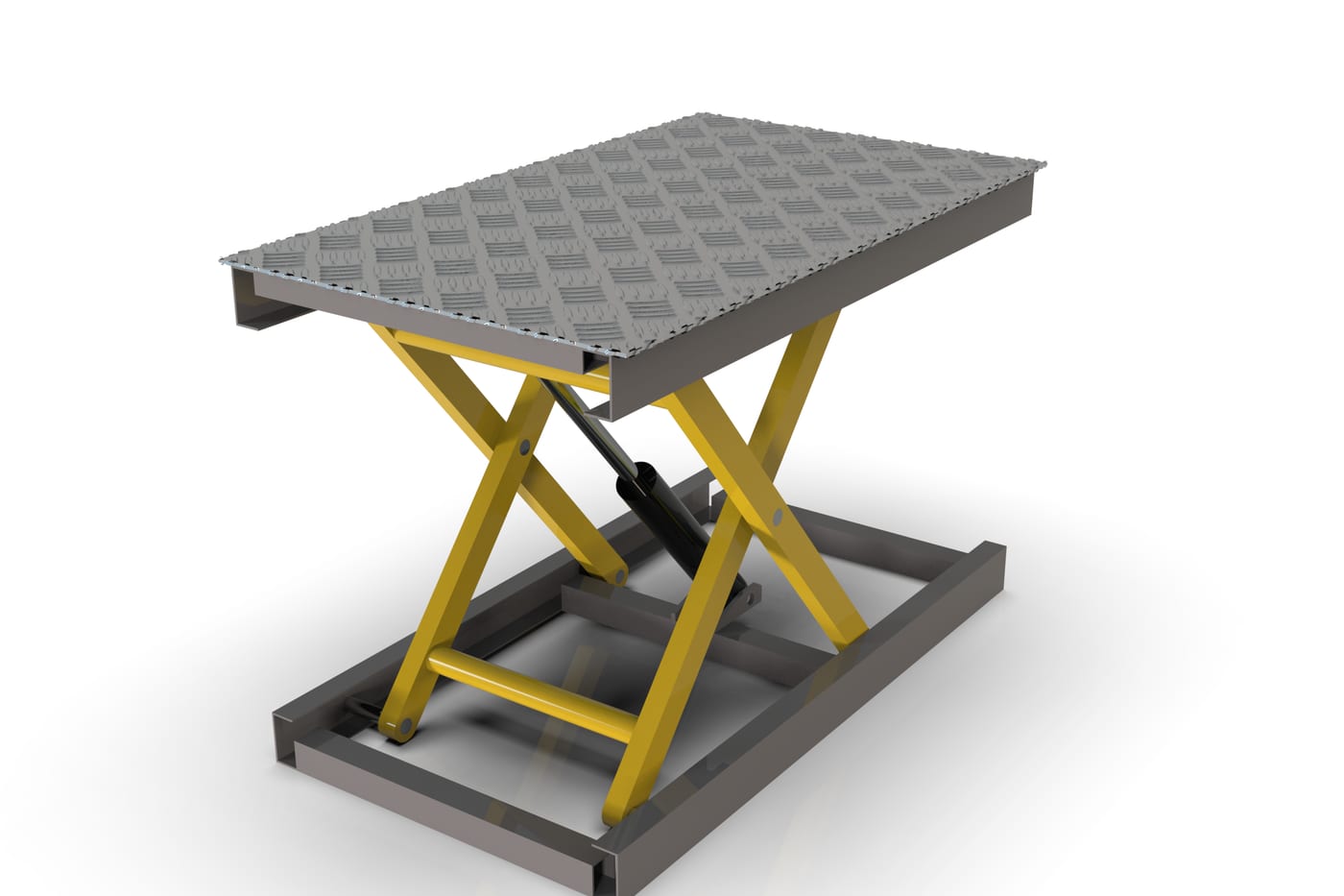
- Hydraulic scissor lift table, 1,000 kg
- Rail trolley, 1,000 kg, with pendulum axle
- Robot vacuum gripper for sheet panels up to 12 kg
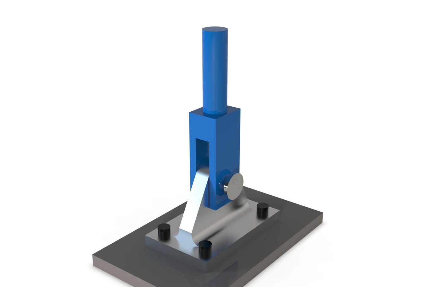
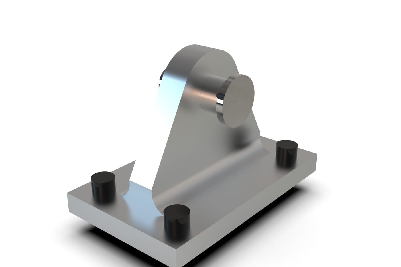
- Machined lug fitting in 7075 aluminium, 45 kN
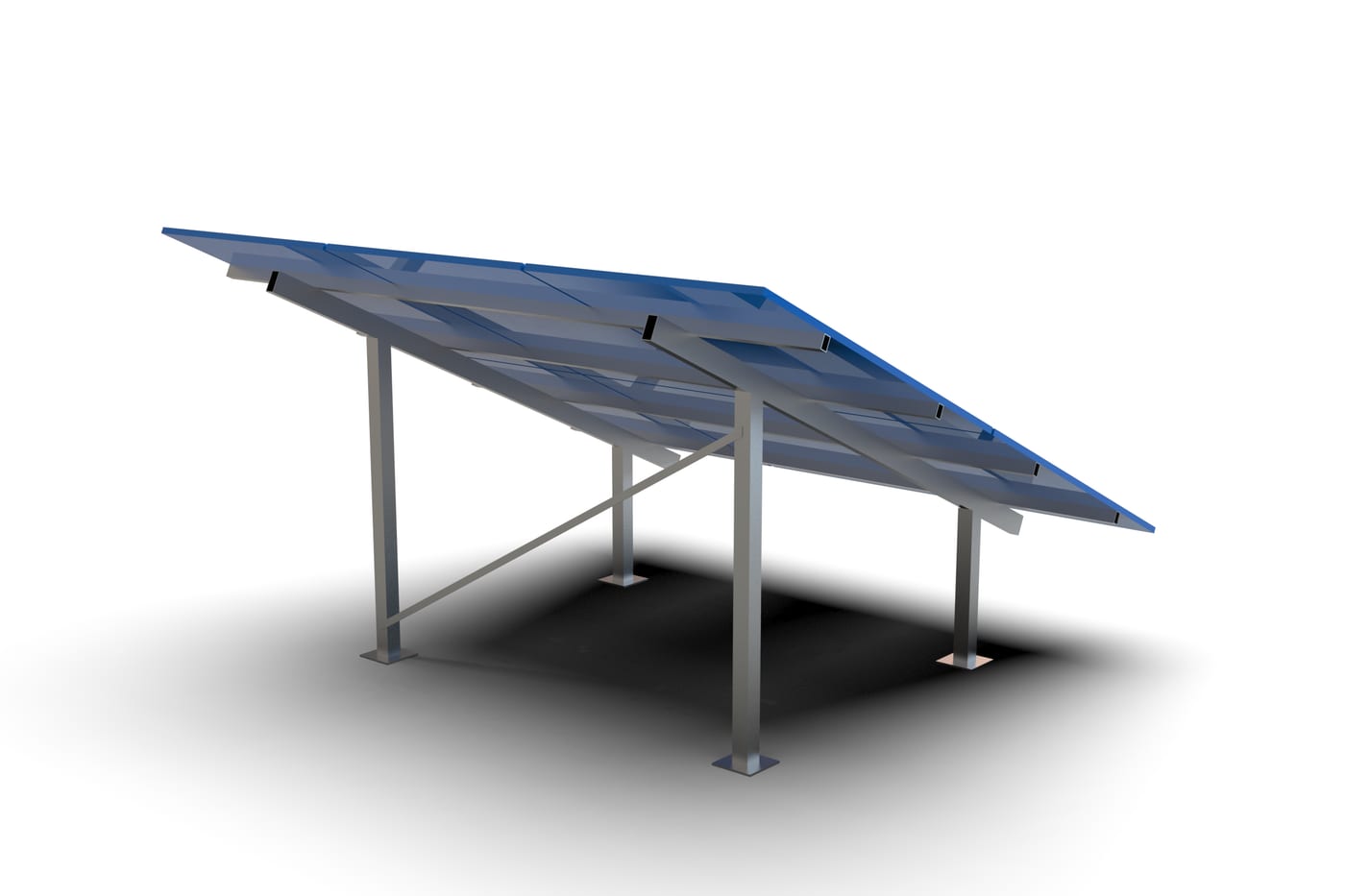
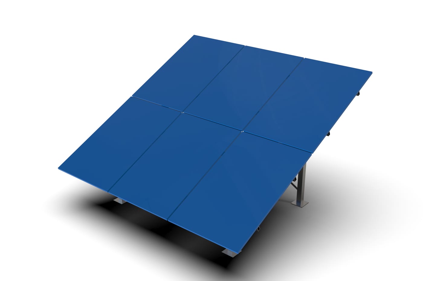
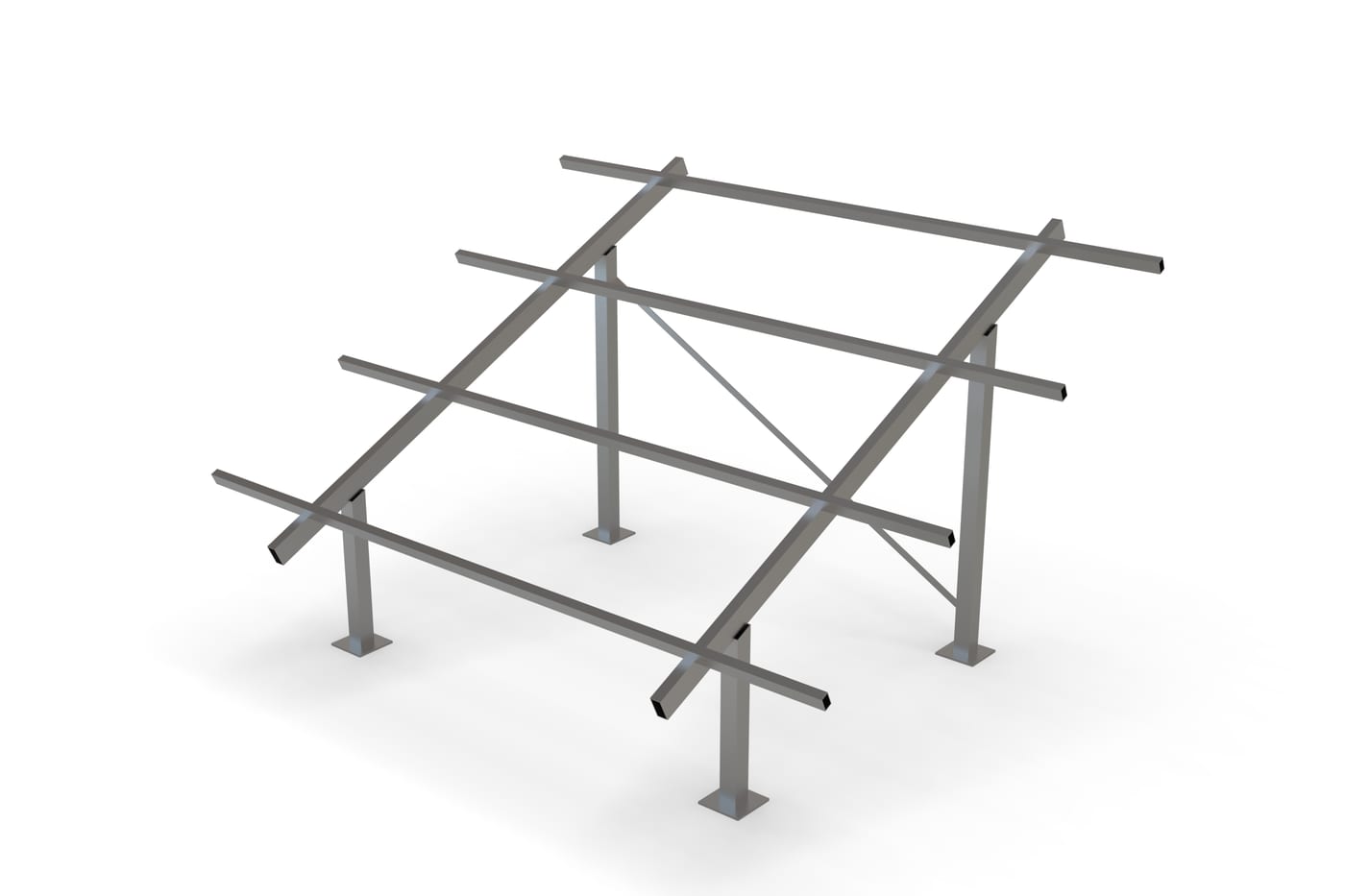
- Ground-mount structure for 6 photovoltaic modules
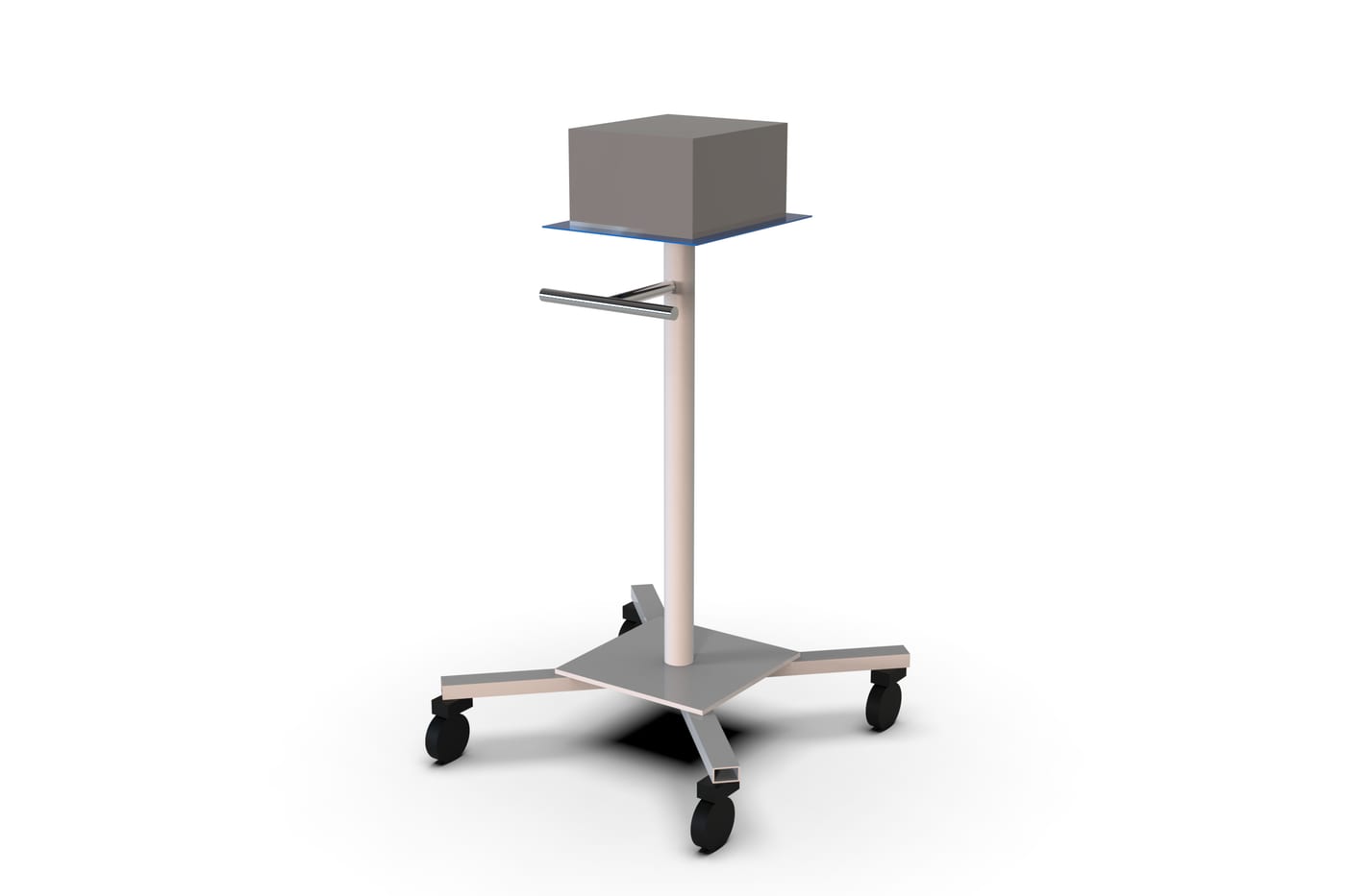
- Device cart on swivel castors, 15 kg at 1.07 m
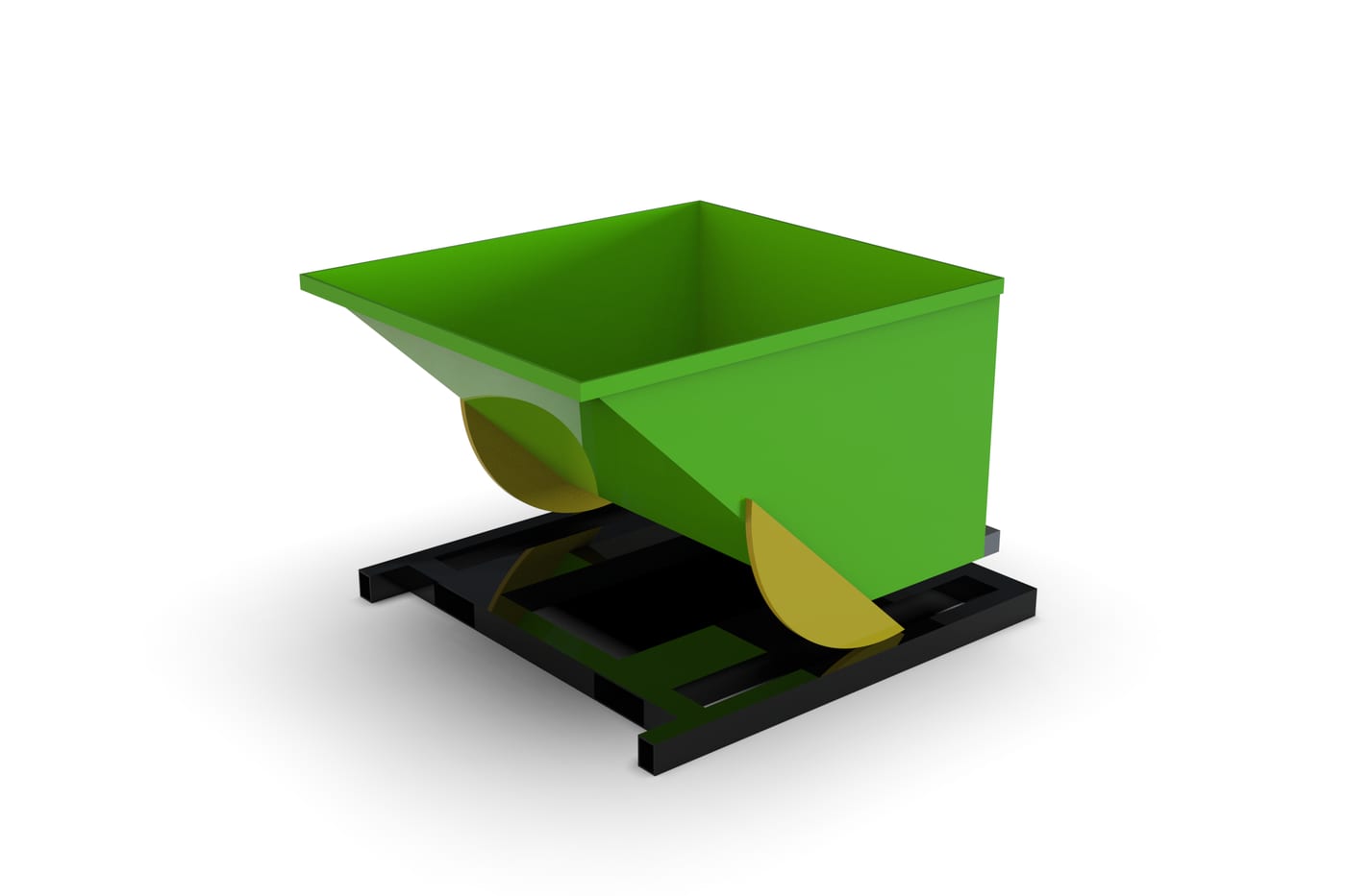
- Self-dumping skip for forklift, 750 L and 1,000 kg
Food processing · TNK-00-000
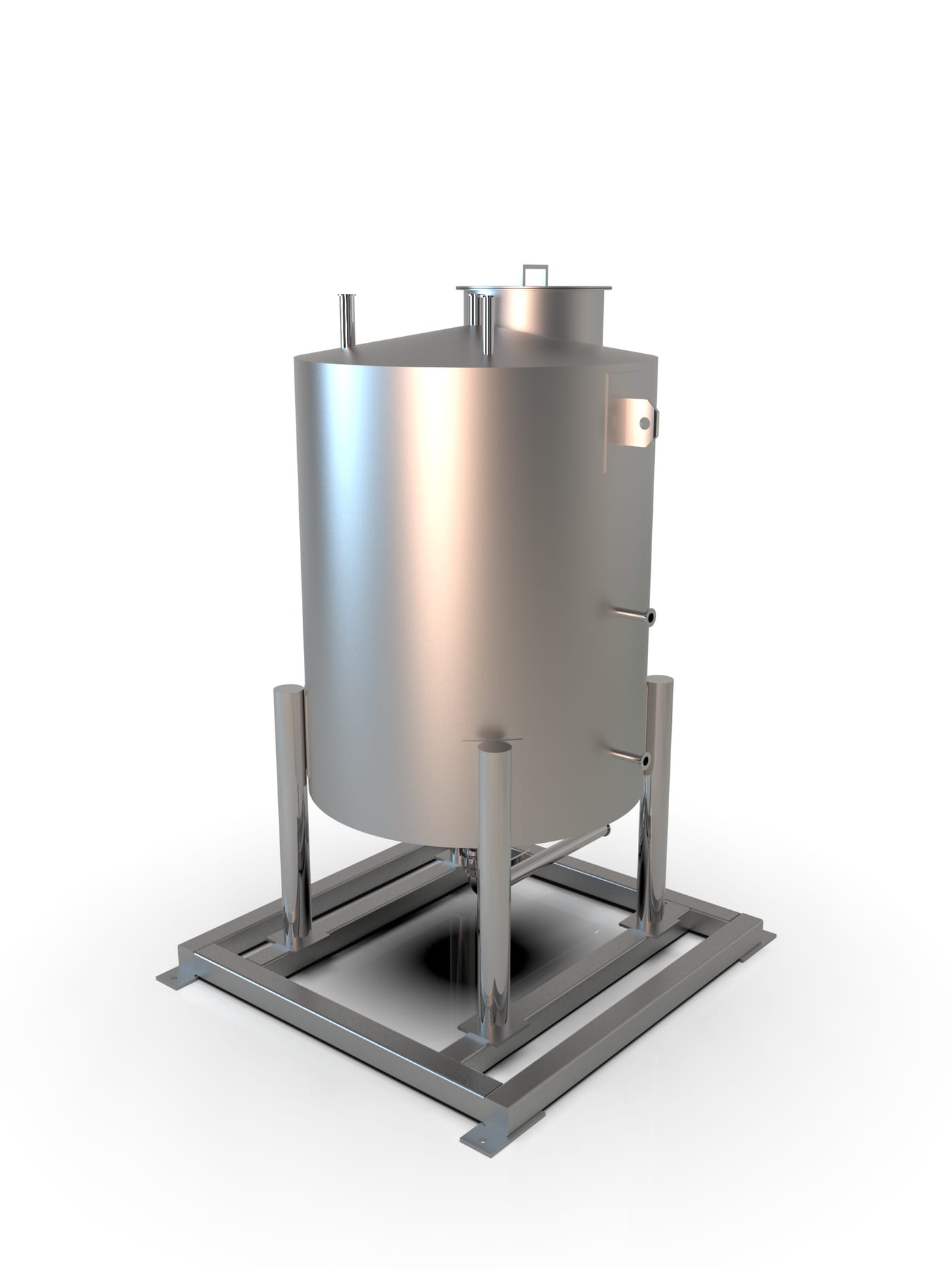
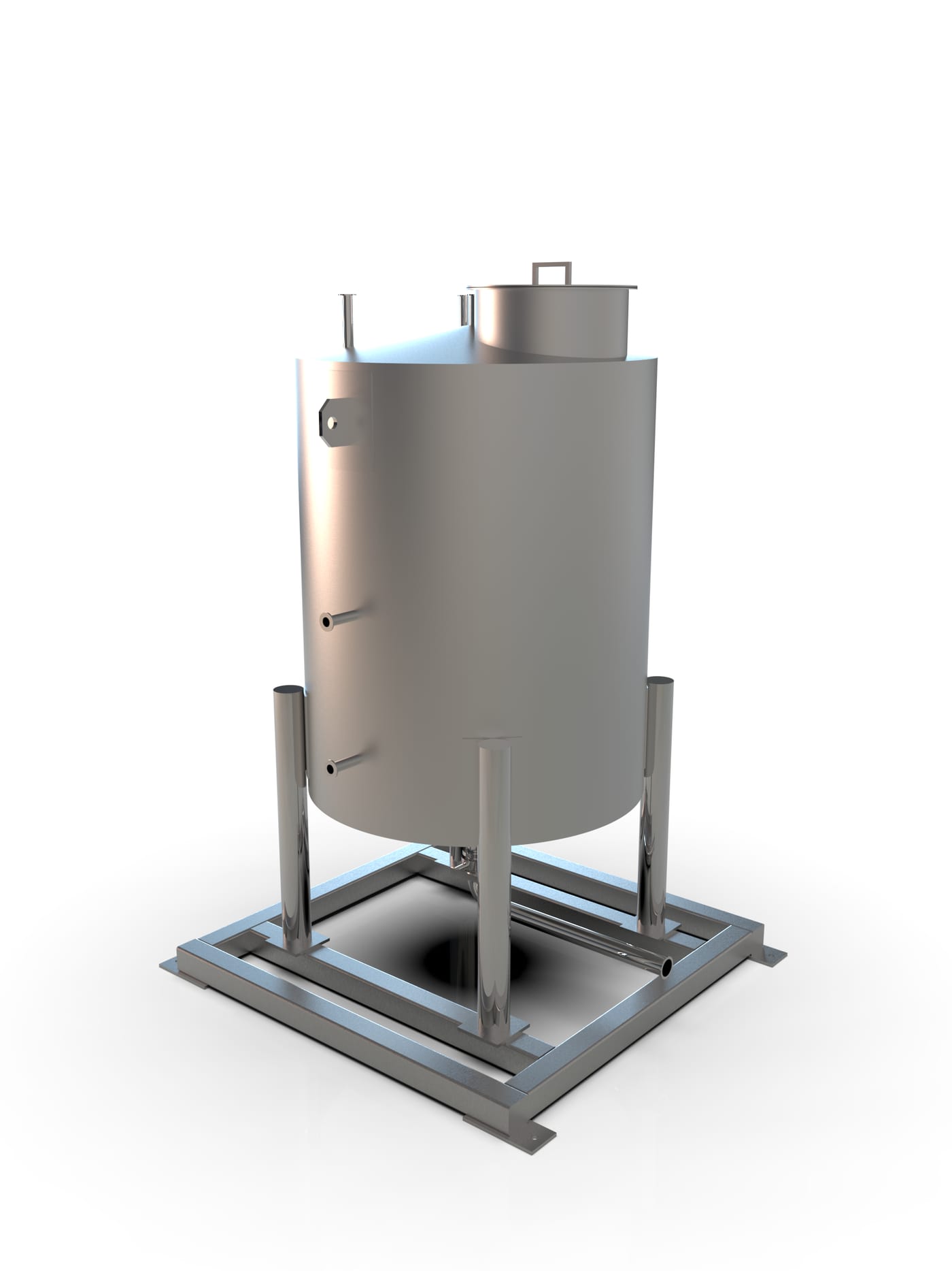
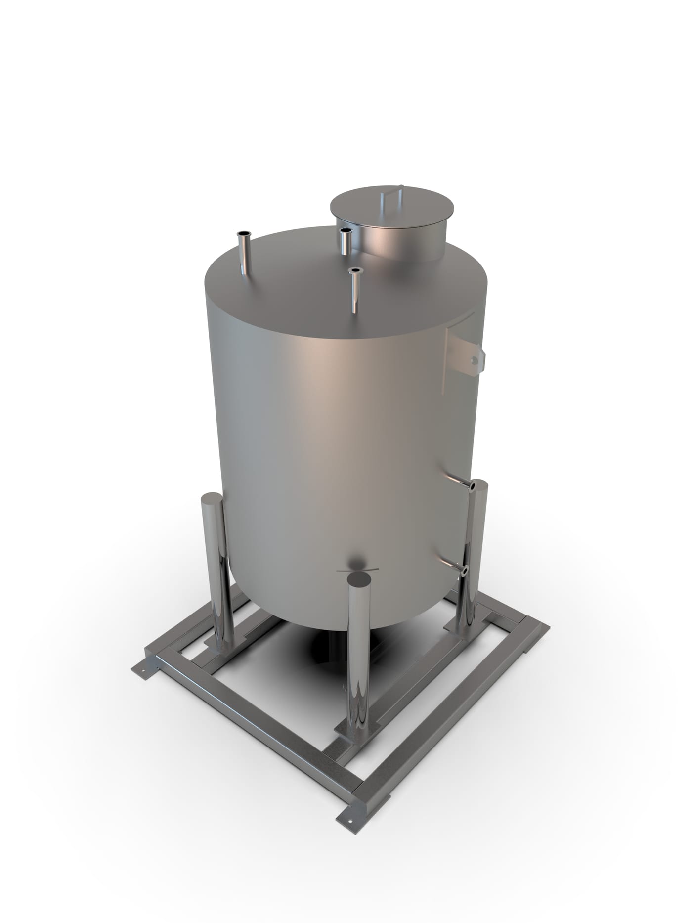
Food-grade stainless steel tank, 1,000 L on skid
3D CAD in SolidWorks · structural verification in ANSYS · hand checks in MATLAB
Atmospheric tank for liquid food products, with a full-drain conical bottom, manway and CIP nozzles. The model is complete with parts, sub-assemblies and part numbering.
Design data
| Capacity | 1,017 L gross, atmospheric |
|---|
| Vessel | ID 1000 × 1250 mm, 3 mm sheet, AISI 304 (1.4301) |
|---|
| Bottom | 15° cone, full drain, DN50 outlet with butterfly valve |
|---|
| Top | 10° cone, DN400 manway, CIP, inlet and vent nozzles |
|---|
| Supports | 4 legs 88.9 × 3 on a 1300 × 1300 skid, SHS 80 × 80 × 4 |
|---|
| Overall size | 1460 × 1320 × 2100 mm |
|---|
| Empty mass | 258 kg, 22 parts in 4 sub-assemblies |
|---|
Structural verification (von Mises)
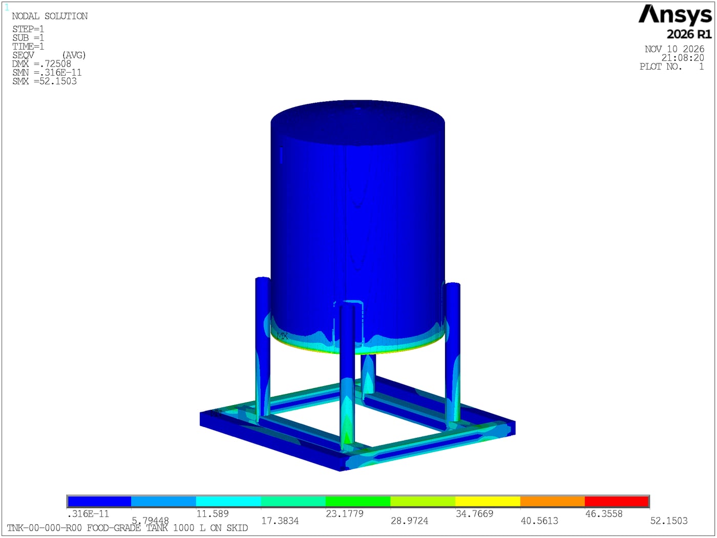
| Full of liquid at 1,200 kg/m³: cone-to-shell junction | 52 MPa |
|---|
| Legs, axial and bending | 40 MPa |
|---|
| Skid beams | 29 MPa |
|---|
| Lifting empty by the lugs, factor 1.5 | 23 MPa |
|---|
| Allowable stress (Rp0.2 / 1.5) | 140 MPa |
|---|
| Minimum margin | 2.7 |
|---|
| Maximum displacement | 0.7 mm |
|---|
Method
Shell-and-beam model with 93,000 elements. Mesh convergence was checked on two densities; support reactions match the total weight within 0.3%. Hand checks agree with the analysis on the cone membrane stress (9.5 vs 9.8 MPa) and on the skid bending stress (27 vs 29 MPa).
Limits. Welds, manway and nozzles are not modelled. Wind, seismic loads, internal pressure, vacuum and thermal loads are not considered.
Project sheet (PDF)
Food processing and handling · CNV-00-000
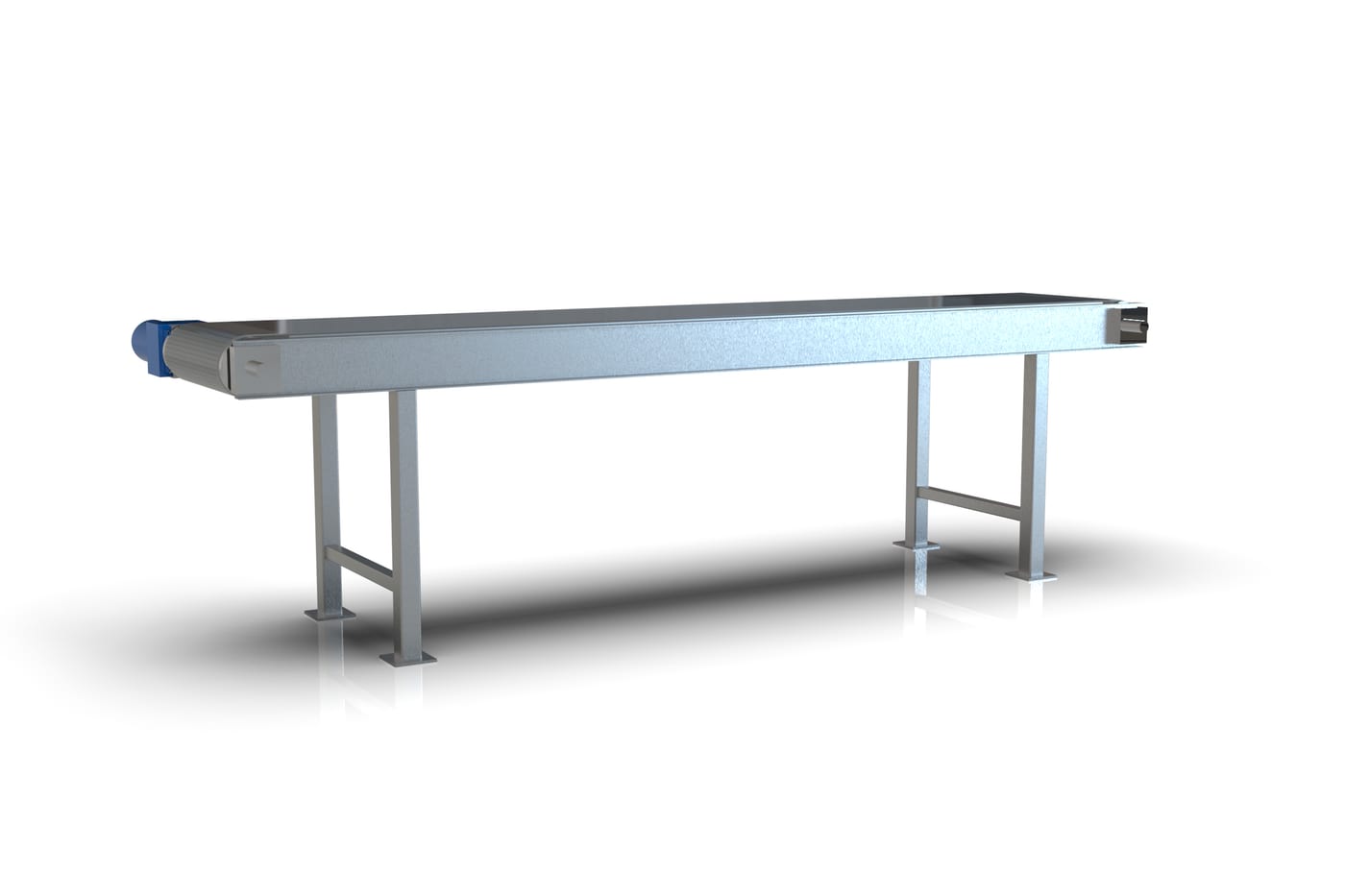
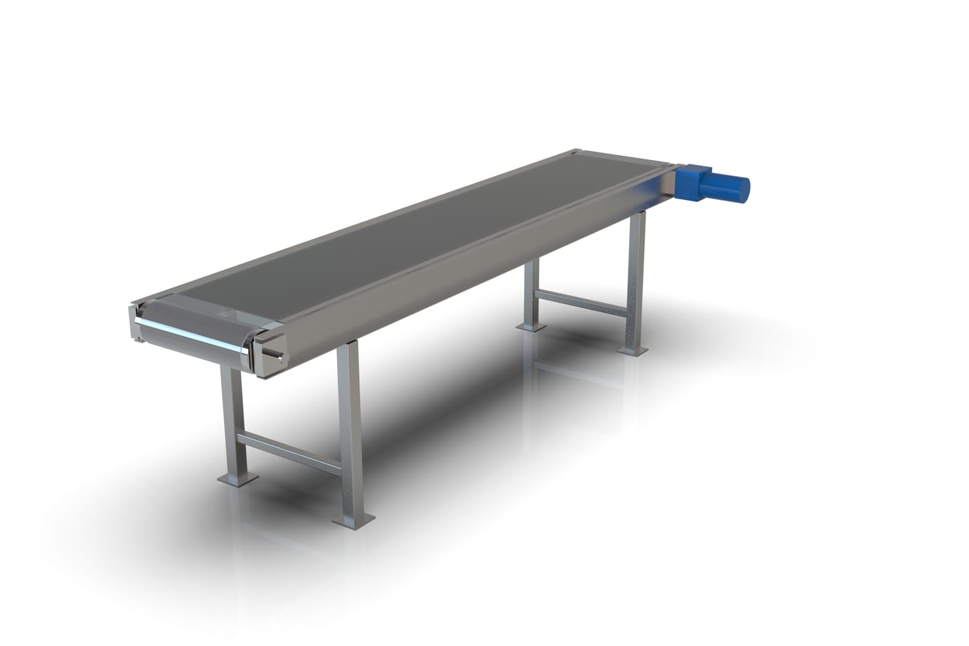
Belt conveyor, 3 m × 500 mm, slider bed
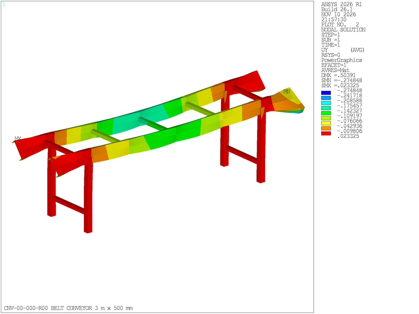
3D CAD in SolidWorks · drive sizing in MATLAB · frame analysis in ANSYS
Belt conveyor 500 mm wide with a stainless steel slider bed, drums, take-up and shaft-mounted gearmotor. The motor is selected by calculation, not by rule of thumb.
Design data
| Conveying length | 3,000 mm between drum axes |
|---|
| Belt | PU, 500 × 3 mm, endless |
|---|
| Transport height | 898 mm |
|---|
| Drums | D160 × 560 mm, 40 mm shaft |
|---|
| Frame | folded channels 150 × 40 × 4, slider bed 5 mm, AISI 304 |
|---|
| Legs | SHS 60 × 60 × 3, two stands |
|---|
| Drive | shaft-mounted gearmotor, 0.25 kW |
|---|
| Overall size | 3166 × 1070 × 898 mm |
|---|
Drive and frame
| Design load | 50 kg/m, 150 kg on the belt |
|---|
| Belt speed | 0.30 m/s (36 rpm) |
|---|
| Peripheral force and drum torque | 456 N · 36.5 Nm |
|---|
| Required power | 171 W, margin 1.5 on the motor |
|---|
| Drive shaft: equivalent stress | 6.7 MPa, fatigue factor 24 |
|---|
| Maximum deflection of the side beams | 0.16 mm |
|---|
| Maximum stress in the frame | 6.0 MPa |
|---|
| First natural frequency | 10.9 Hz |
|---|
Method
Belt tensions, torque and power calculated with a friction coefficient of 0.30 on the bed and an efficiency of 0.80. Frame verified with a beam model of 778 elements; the hand check on the side beam gives 5.6 MPa and 0.18 mm, in agreement with the analysis.
Limits. The project does not include guards, protection of drawing-in points and the risk assessment, which depend on the installation.
Project sheet (PDF)
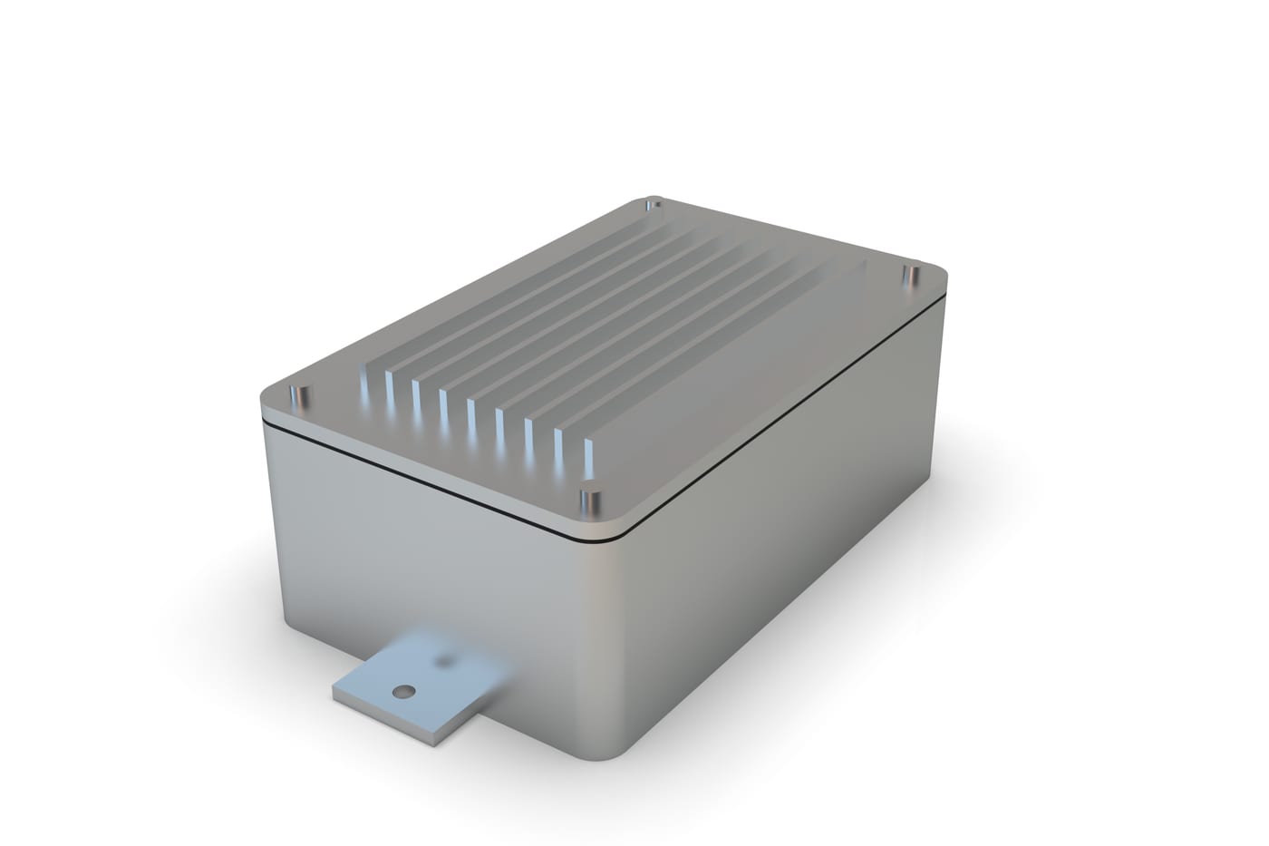
Components and enclosures · ENC-00-000
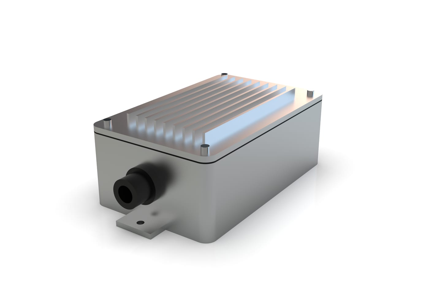
IP65 aluminium enclosure with a finned lid
3D CAD in SolidWorks · thermal network in MATLAB · thermal analysis in ANSYS
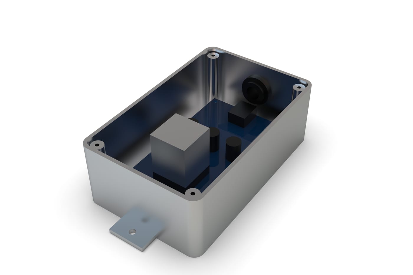
Enclosure machined from solid for a module dissipating 10 W. The mechanical design solves two problems at once: sealing and heat removal, with an aluminium bridge carrying the heat to the finned lid.
Design data
| Size | 160 × 100 × 66 mm |
|---|
| Material | aluminium EN AW-6061 |
|---|
| Thickness | walls 3 mm, lid 4 mm |
|---|
| Sealing | 1 mm silicone gasket, lid lip, 4 × M3 screws |
|---|
| Cable entry | M20 gland |
|---|
| Board | 132 × 72 mm on 4 posts |
|---|
| Cooling | 9 fins, natural convection |
|---|
Temperatures at 40 °C ambient
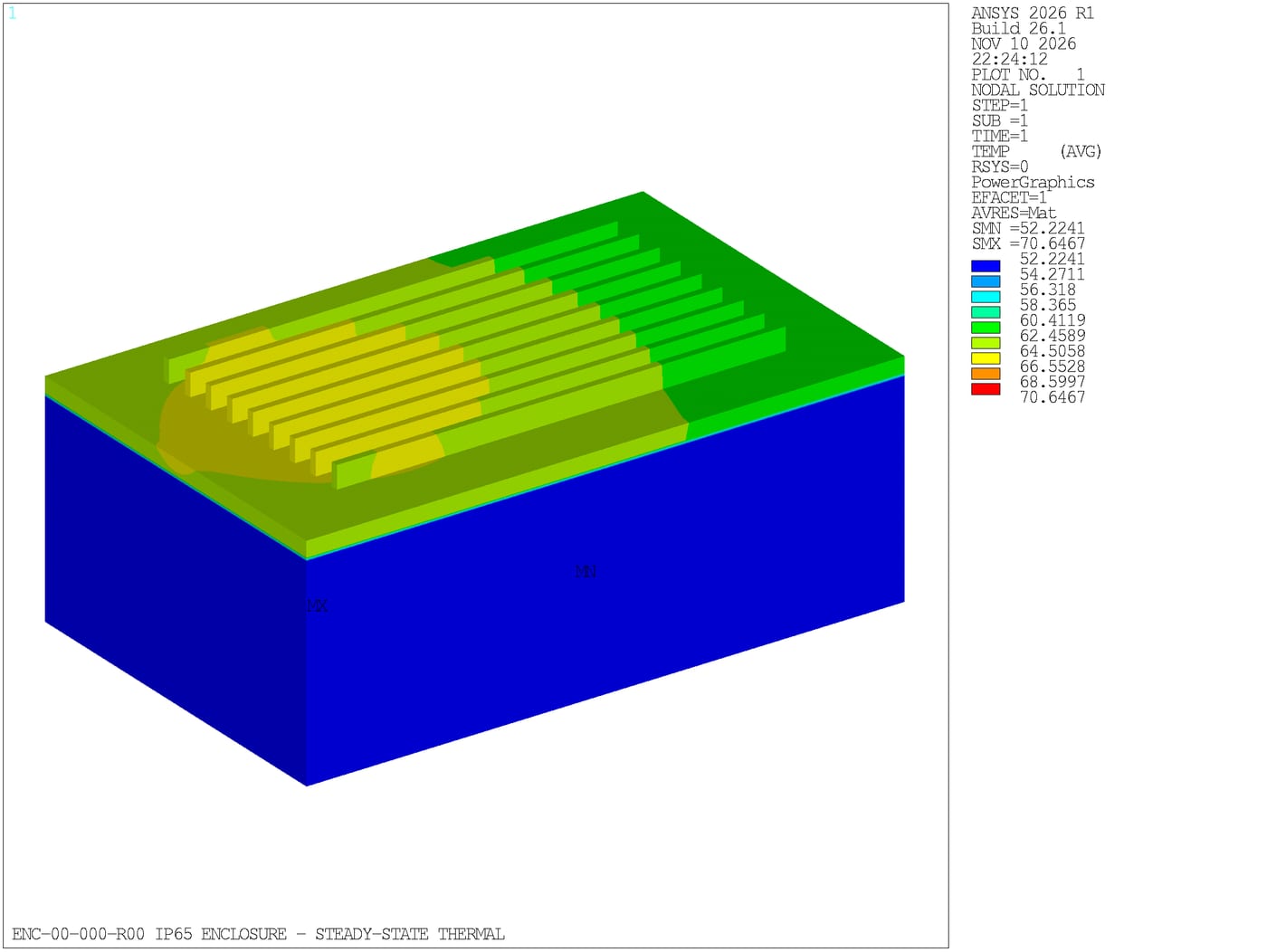
| Dissipating module | 70.6 °C (hand check 67.6 °C) |
|---|
| Finned lid | 61 to 66 °C (hand check 63.1 °C) |
|---|
| Body | 52 to 53 °C (hand check 52.9 °C) |
|---|
| Heat through the lid | 5.4 W |
|---|
| Heat through the body | 4.6 W |
|---|
| Without the heat bridge, lid only | 83 °C |
|---|
Method
Steady-state conduction model with 62,000 elements. Natural convection and radiation are lumped into a coefficient of 8 W/m²K on the outer surfaces. Internal air and the board are not modelled, which is conservative.
Limits. The studio designs the enclosure and verifies it thermally and mechanically. The board and the components inside are envelope volumes only.
Project sheet (PDF)
Handling and lifting · LFT-00-000
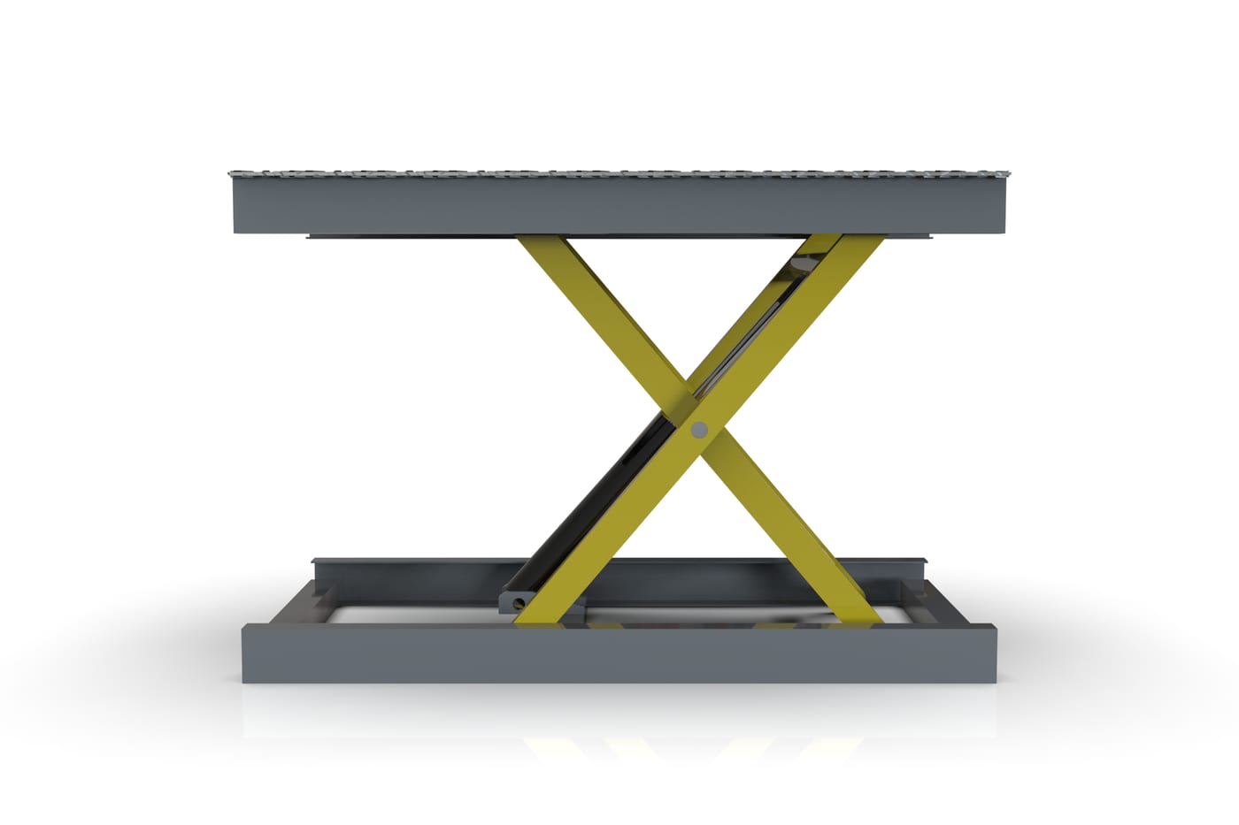
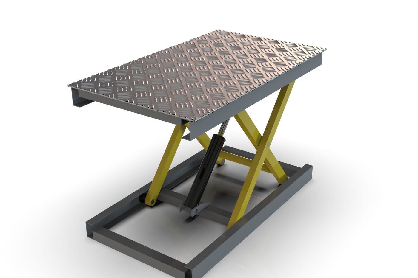
Hydraulic scissor lift table, 1,000 kg
3D CAD in SolidWorks · kinematics and statics in MATLAB · beam analysis in ANSYS
Hydraulic single-scissor lift table, with one cylinder and rollers retained in C-sections. Cylinder, pins and arms are sized on the worst position, which is with the table lowered.
Design data
| Rated load | 1,000 kg (× 1.25 in checks) |
|---|
| Platform | 1360 × 800 mm, 6 mm chequer plate |
|---|
| Height | 227 to 917 mm |
|---|
| Lift | single scissor, 1 cylinder |
|---|
| Cylinder | bore 80 mm, stroke 352 mm |
|---|
| Maximum pressure | 173 bar, table lowered |
|---|
| Arms | flat bar 60 × 40, S355 |
|---|
| Pins | 30 mm diameter, C45 |
|---|
| Rollers | 60 mm diameter, retained in C 70 × 50 sections |
|---|
| Mass | 208 kg, no interferences |
|---|
Results for one scissor side (load × 1.25)
| Cylinder force, table lowered | 43.4 kN (hand check 43.4 kN) |
|---|
| Cylinder force, table raised | 8.79 kN (hand check 8.79 kN) |
|---|
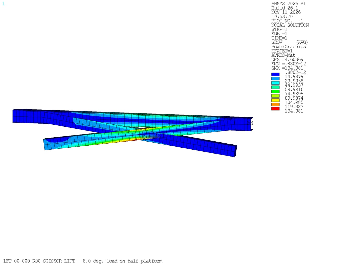
| Arm stress, worst case | 151 MPa at the hole (hand check 153 MPa) |
|---|
| Allowable stress (0.67 Rp) | 231 MPa |
|---|
| Pin shear | 61 MPa, allowable 173 MPa |
|---|
| Maximum platform deflection | 5.9 mm |
|---|
Method
Closed-form statics of the scissor from 8 to 50 degrees, with the load centred and on half platform, to size cylinder, pins and arms. The worst positions are then checked with a planar beam model of 183 elements: pinned joints, rollers free to slide, cylinder as a link. Cylinder forces match the hand model. Worst case: table lowered, load on half platform.
Limits. The model is planar and static: welds, lateral stability and fatigue are not considered, and the weight of the arms is neglected. The power unit, valves and safety devices are not part of the study.
Project sheet (PDF)
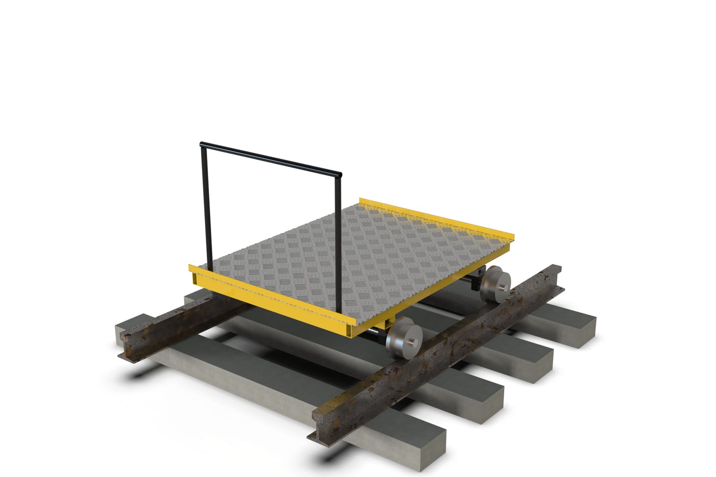
Railway · RTR-00-000
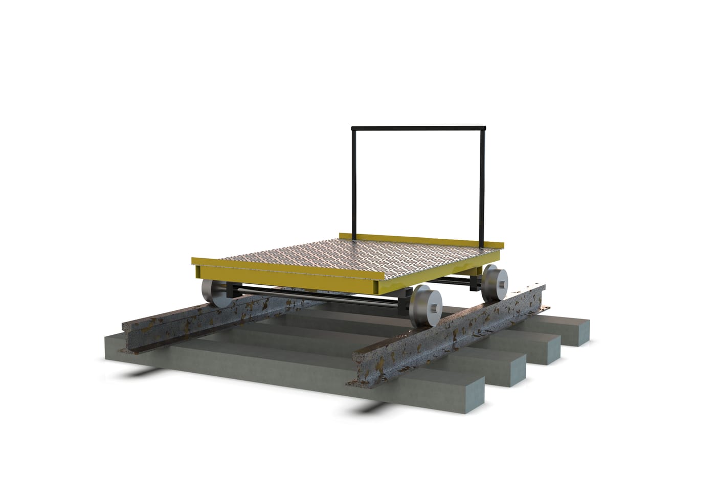
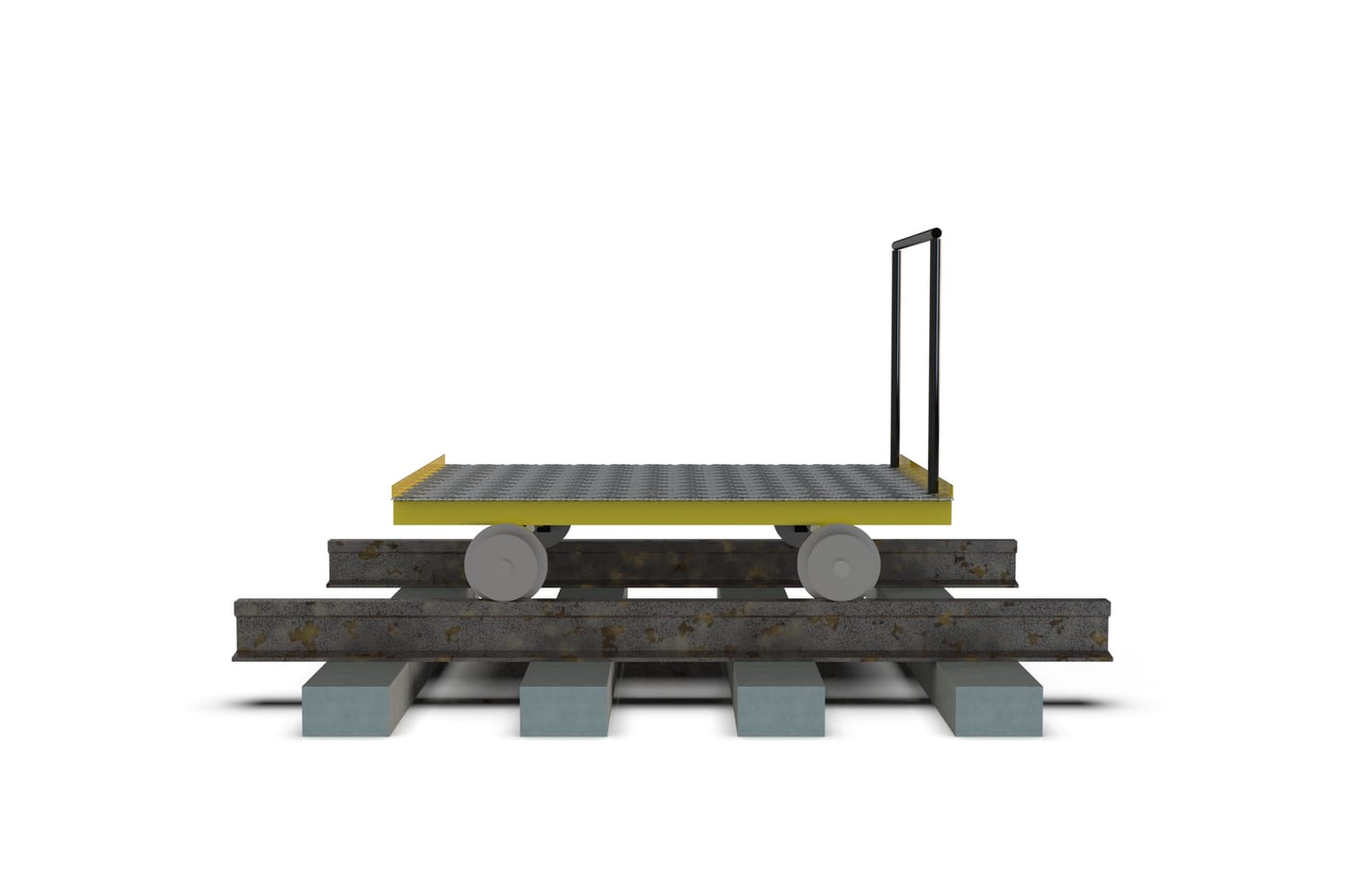
Rail trolley, 1,000 kg, with pendulum axle
3D CAD in SolidWorks · wheel loads and hand checks in MATLAB · beam analysis in ANSYS
Push trolley for tools and materials on 1435 mm gauge track. The rear axle swings on a central pivot: the trolley rests on three points and all four wheels stay loaded on twisted track, the condition in which a rigid frame unloads a wheel.
Design data
| Rated load | 1,000 kg (× 1.25 in checks) |
|---|
| Track gauge | 1435 mm |
|---|
| Deck | 1700 × 1300 mm, 4 mm chequer plate |
|---|
| Deck height | 294 mm above top of rail |
|---|
| Wheelbase | 1000 mm |
|---|
| Wheels | 200 mm diameter, 250 mm flange, C45 |
|---|
| Axles | 50 mm diameter, C45 |
|---|
| Rear axle | pendulum on a 30 mm pin, ± 12 mm at the wheel |
|---|
| Frame | RHS 80 × 40 × 4, S355 |
|---|
| Mass | 339 kg, no interferences |
|---|
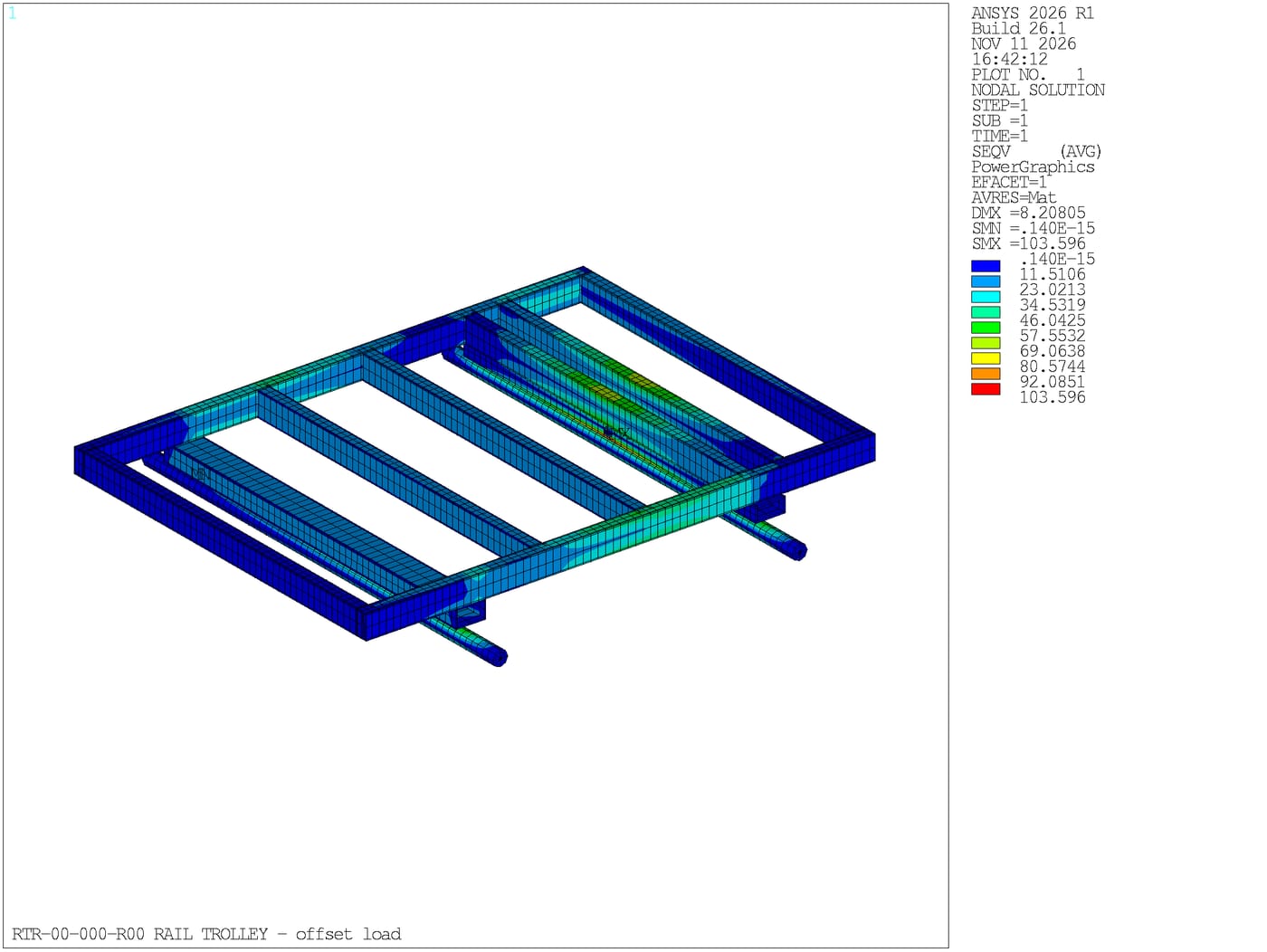
Results with offset load (150 mm towards the pendulum axle, 240 mm sideways)
| Front wheel loads | 4674 and 724 N (hand check 4702 and 752 N) |
|---|
| Rear wheel loads | 4554 N each (hand check 4567 N) |
|---|
| Axles, rotating bending | 56 MPa (hand check 56 MPa), fatigue 115 MPa |
|---|
| Pendulum axle rocker beam | 104 MPa (hand check 109 MPa at the hole) |
|---|
| Pivot cross members | 67 MPa (hand check 74 MPa) |
|---|
| Allowable stress (0.67 Rp) | 231 MPa |
|---|
| Track twist absorbed with all wheels loaded | 24 mm over the wheelbase |
|---|
| Push force at full load, level track | 131 N |
|---|
Method
Wheel loads on three-point support, axle fatigue in rotating bending, rocker beam, pivot pin and push force are checked by hand, with the load centred and offset. Frame, rocker and axles are then verified with a 3D beam model of 680 elements: bearings as translation-only couplings, one locating and one floating, pivot free to swing. Wheel loads match the hand model within 1%.
Limits. The beam model does not consider welds or the contribution of the deck plate. With the load offset sideways beyond 362 mm a front wheel unloads and the rocker end stop takes over. Brake, wheel-rail contact and the requirements for use on a network are not part of the study.
Project sheet (PDF)
Automotive · VGR-00-000
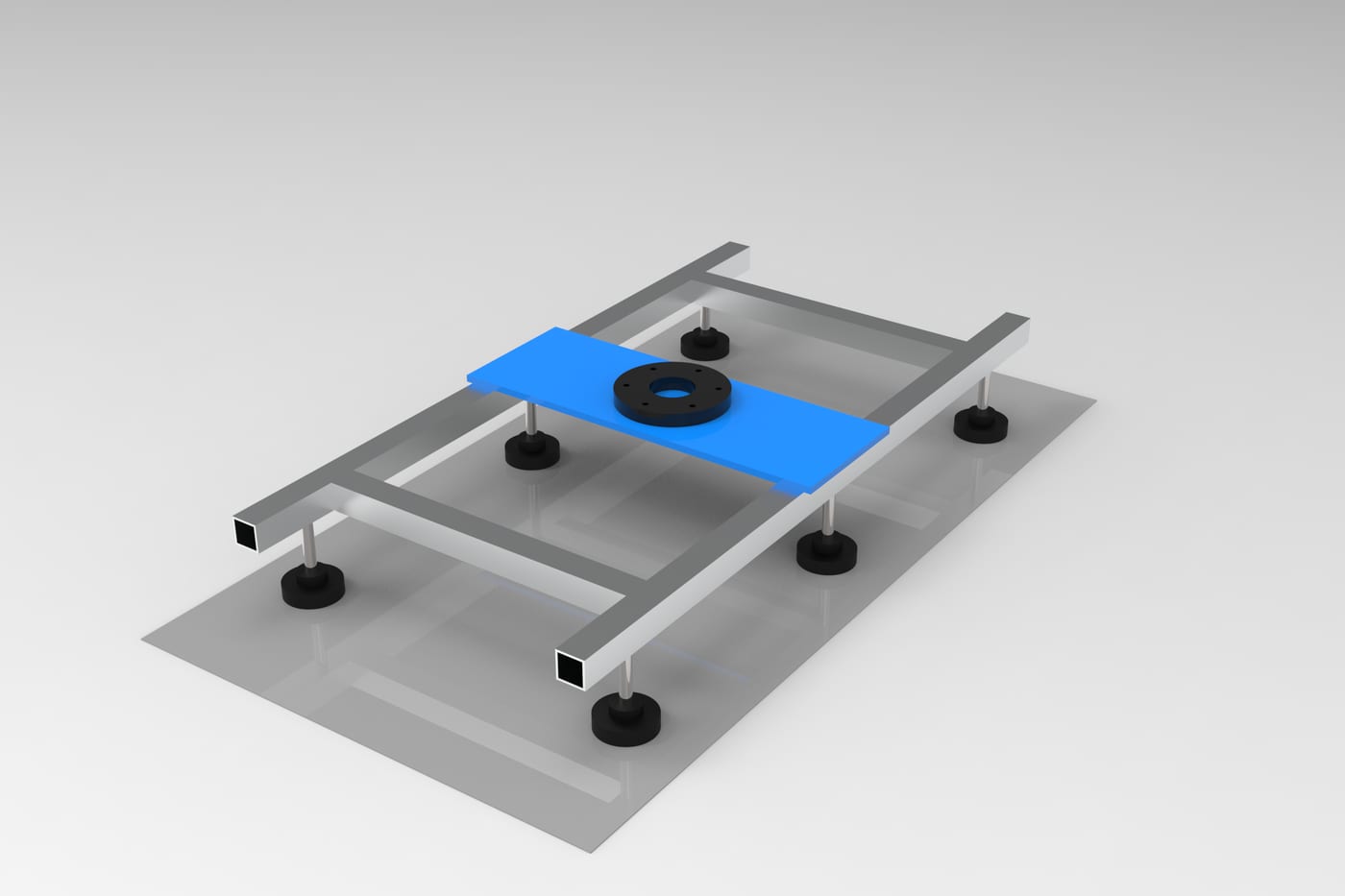
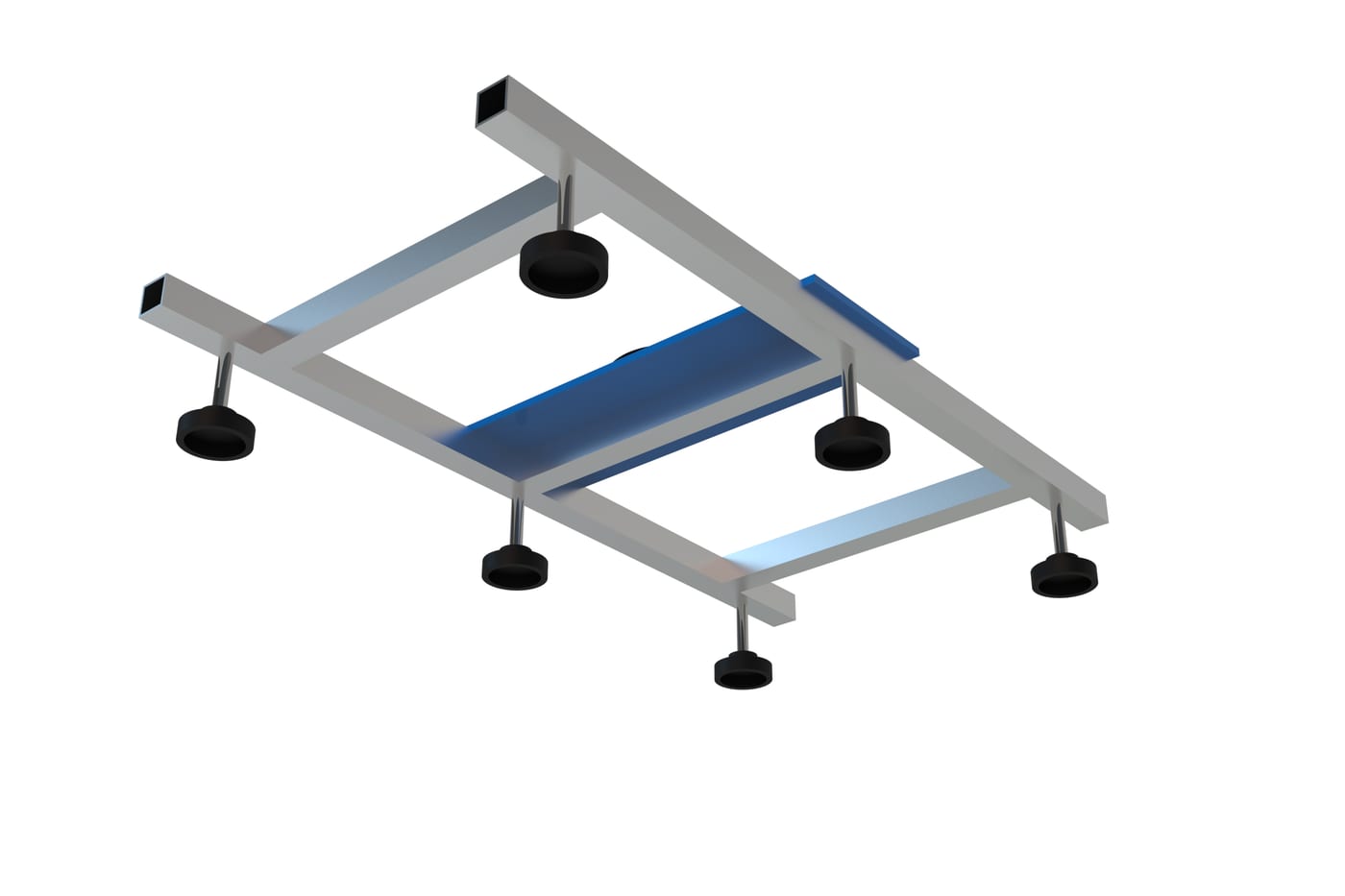
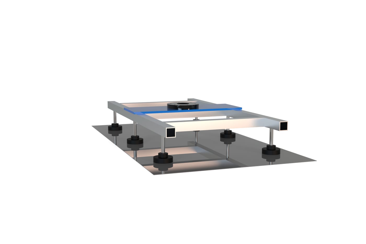
Robot vacuum gripper for sheet panels up to 12 kg
3D CAD in SolidWorks · holding force and hand checks in MATLAB · beam and modal analysis in ANSYS
End-of-arm tool for robotic handling of sheet panels: aluminium tube frame, six vacuum cups and robot flange adapter. The useful output for whoever programs the robot is the allowed accelerations, calculated with the friction of oiled sheet and also with one cup lost.
Design data
| Payload | sheet panel up to 12 kg |
|---|
| Panel size | up to 1300 × 700 mm |
|---|
| Cups | 6 × 80 mm, 60% vacuum |
|---|
| Theoretical holding force | 1,810 N |
|---|
| Frame | tube 40 × 40 × 3, EN AW-6063 |
|---|
| Frame size | 1100 × 540 mm |
|---|
| Robot flange | PCD 125 mm, 6 × 9 mm holes, 63 mm pilot |
|---|
| Gripper mass | 9.4 kg, no interferences |
|---|
| Wrist load | 21.4 kg, centre of gravity 126 mm below the flange |
|---|
Holding and stiffness
| Safety at 2 g vertical | 5.1 (4.3 with one cup lost) |
|---|
| Safety at 1 g horizontal | 2.6 (2.1 with one cup lost) |
|---|
| Safety with panel vertical, 0.5 g | 2.05 (1.7 with one cup lost) |
|---|
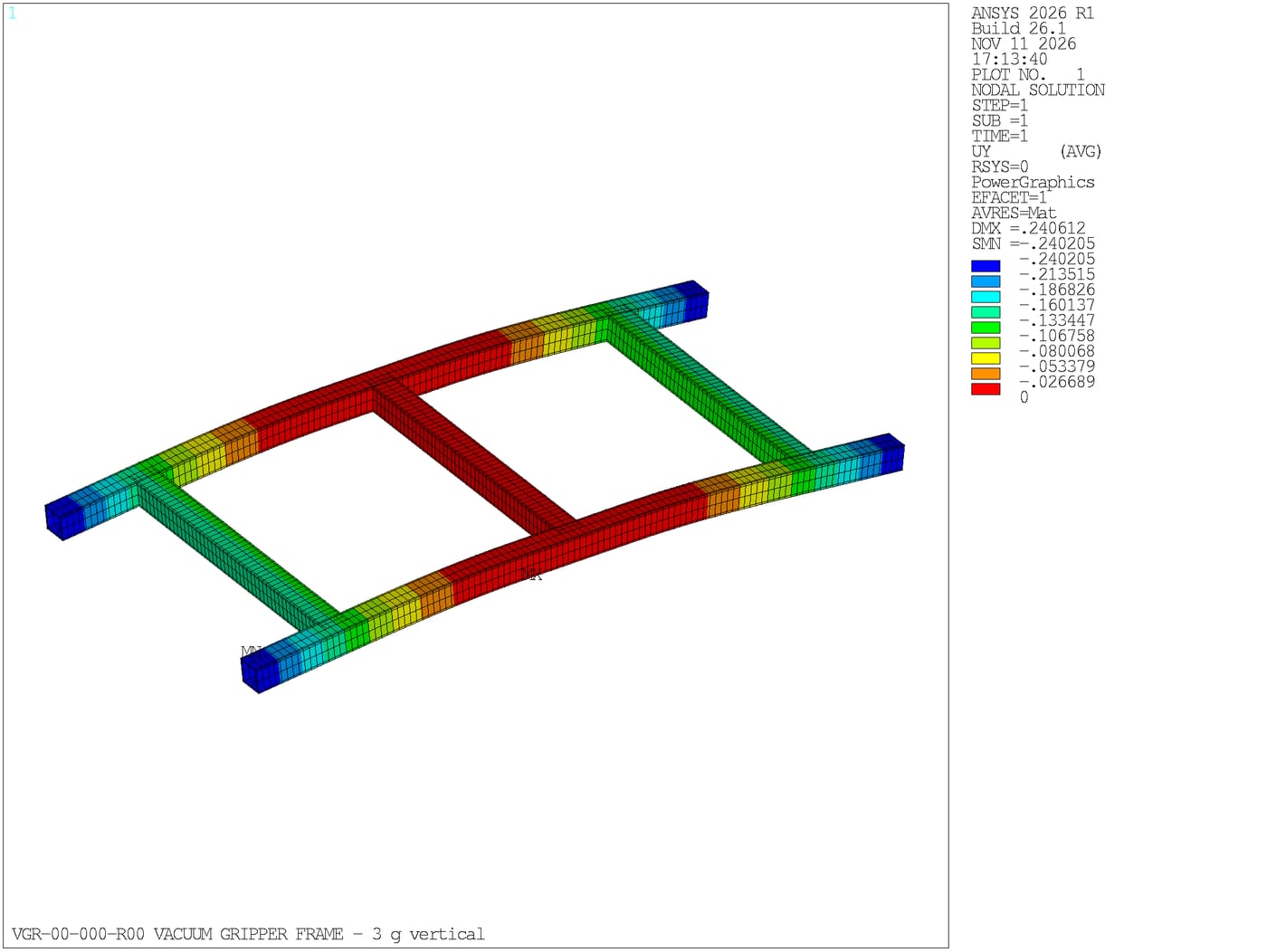
| Corner cup deflection at 3 g | 0.17 mm (hand check 0.16 mm) |
|---|
| Frame stress at 3 g | 5.7 MPa (hand check 5.6 MPa) |
|---|
| First natural frequency | 67 Hz (hand check 68 Hz) |
|---|
Method
Holding force from cup area and vacuum level, with friction 0.2 for oiled sheet: this gives the accelerations the robot may use with a safety factor of 2. The frame is stiffness-driven: a beam model of 376 elements, with cups and panel share as point masses and a rigid mounting plate, gives the deflection at 3 g and the natural frequencies. The hand cantilever model matches within 5%.
Limits. Holding force is theoretical: leakage, porosity and panel deformation are not considered. With the panel vertical and one cup lost the safety factor drops to 1.7, below the required value of 2. The vacuum circuit and its monitoring are not part of the study.
Project sheet (PDF)
Aerospace · LUG-00-000
Machined lug fitting in 7075 aluminium, 45 kN
3D CAD in SolidWorks · lug hand analysis in MATLAB · solid finite element analysis in ANSYS
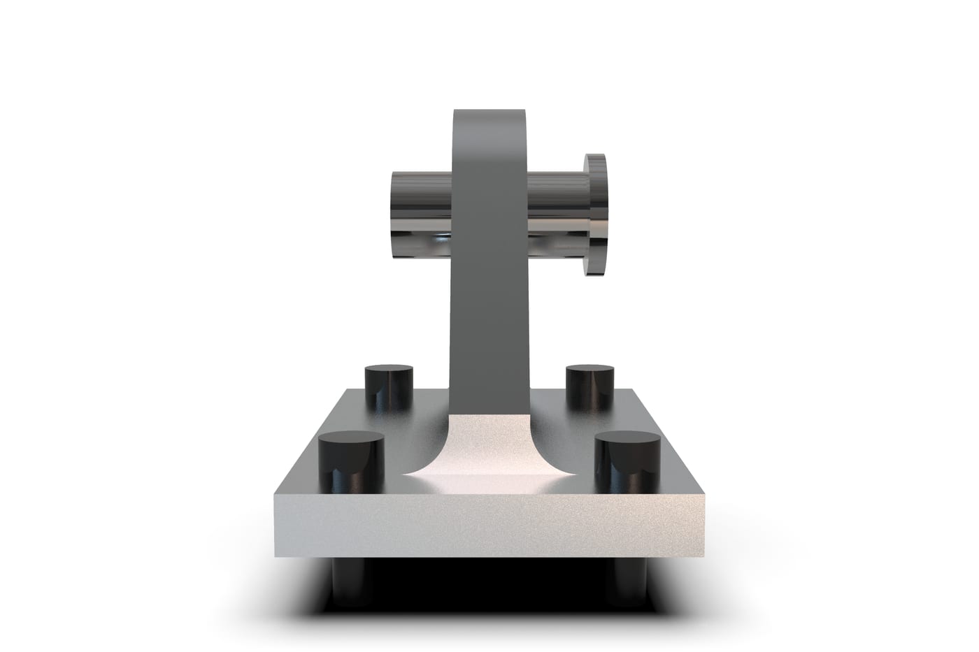
Structural fitting machined from plate, with a lug for a 20 mm pin and a four-screw base. It is sized on the limit load, with margins of safety expressed the way the sector does: margin on yield at limit load and on rupture at ultimate load.
Design data
| Limit load | 45 kN at 20° off the lug axis |
|---|
| Ultimate load | 67.5 kN (× 1.5) |
|---|
| Material | EN AW-7075 T651 plate |
|---|
| Strength | Rp0.2 470 MPa, Rm 540 MPa |
|---|
| Lug | 16 mm thick, 24 mm radius, 20 mm pin |
|---|
| Base | 130 × 80 × 12 mm, 10 mm fillets |
|---|
| Fasteners | 4 × M8 class 12.9 screws |
|---|
| Mass | 0.56 kg, no interferences |
|---|
| Limit load to mass | 80 kN/kg |
|---|
Results at limit load
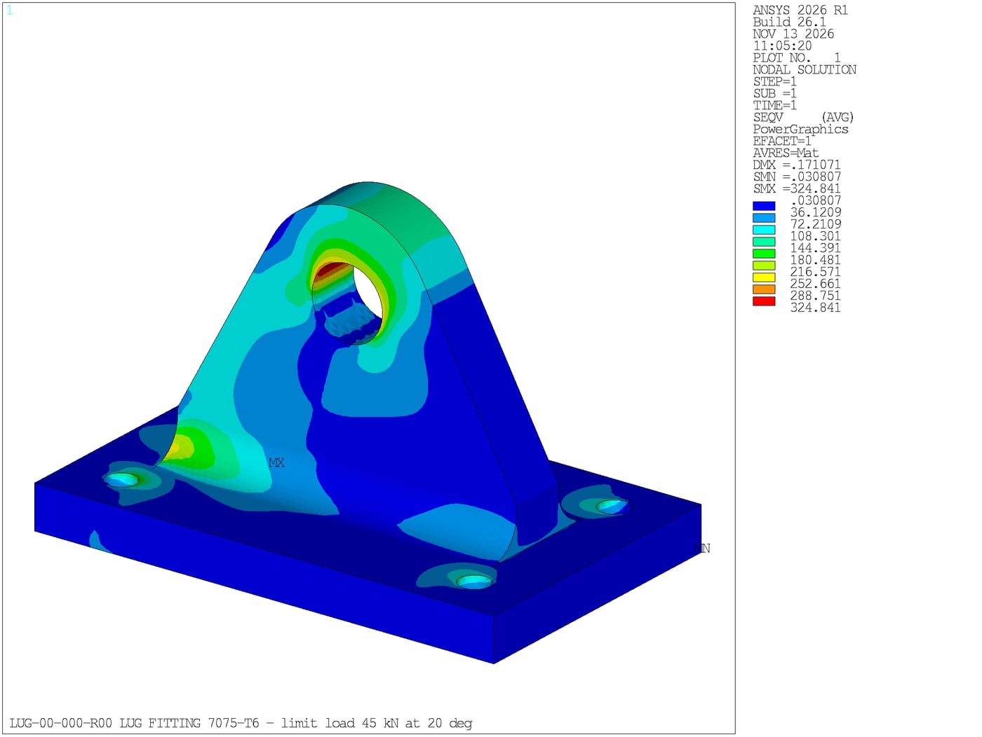
| Peak stress at the pin hole | 325 MPa (hand check 301 MPa, Kt 3.0) |
|---|
| Fillets between lug and base | 240 MPa |
|---|
| Margin on yield, limit load | +0.45 |
|---|
| Margin on rupture, ultimate load | +0.11 on the elastic peak |
|---|
| M8 screws at ultimate load | margin +0.94 |
|---|
| Mesh check | 307 to 312 MPa at nodes between 101,000 and 262,000 elements |
|---|
Method
First the classic lug checks by hand: net section with stress concentration, shear tear-out, bearing and screw loads from the offset force. Then a solid model of 262,000 tetrahedra: the pin loads half the hole with a cosine pressure, the screws restrain the base in shear with a clamped ring under each head. The peak changes by 1.4% between two meshes; the hand value is 7% below the surface peak, which is the one used for the margins.
Limits. The margin on rupture is taken on the elastic peak, so it is conservative. The fatigue estimate (factor 1.9 with a cycle from 0 to 40% of limit load) is indicative: it uses literature data and does not consider fretting at the hole. Screw seats in the model are ideal restraints. It is not a qualified or certified part.
Project sheet (PDF)
Energy · PVS-00-000
Ground-mount structure for 6 photovoltaic modules
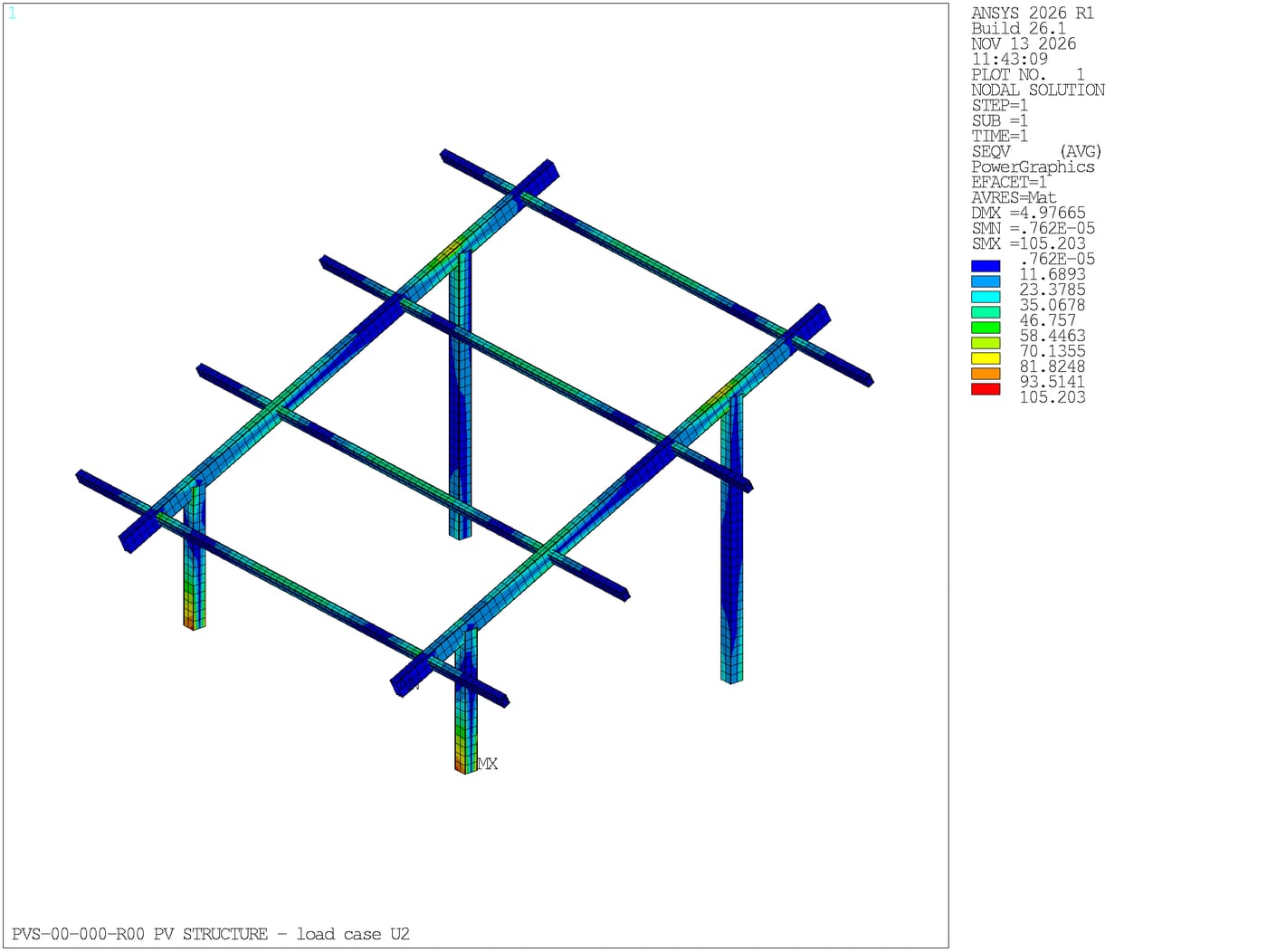
3D CAD in SolidWorks · loads and hand checks in MATLAB · 3D beam analysis in ANSYS
Galvanised steel tube structure with a fixed 25° tilt: two frames, four purlins and a brace. The governing case is not snow but wind uplift: it unloads the posts and puts the feet in tension, and that is what sizes the foundation.
Design data
| Modules | 6 × 1722 × 1134 mm, 22 kg each |
|---|
| Tilt | fixed, 25° |
|---|
| Table | 3.46 × 3.44 m |
|---|
| Posts | RHS 80 × 80 × 3 |
|---|
| Rafters | RHS 100 × 50 × 3 |
|---|
| Purlins | RHS 60 × 40 × 3 |
|---|
| Steel | S355, hot-dip galvanised |
|---|
| Structure mass | 153 kg, no interferences |
|---|
| Assumed loads | snow 0.80 kN/m², wind +1.00 and −1.30 kN/m² |
|---|
Results with the design combinations
| Total load, snow plus wind | 26.3 kN vertical and 4.5 kN horizontal (same values by hand) |
|---|
| Purlins, snow plus wind | 93 MPa (hand check 109 MPa) |
|---|
| Posts, wind uplift | 105 MPa |
|---|
| Highest utilisation | 0.30 of the 355 MPa limit |
|---|
| Uplift at the rear foot | 6.7 kN: 764 kg ballast or ground screw |
|---|
| Purlin deflection in service | 3.0 mm |
|---|
Method
Loads per purlin from assumed design values of snow and wind, combined as 1.35 G + 1.5 snow + 0.9 wind and 1.0 G + 1.5 wind uplift. A 3D beam model of 505 elements, with posts fixed at the base, gives stresses, deflections and foot reactions for each combination. The hand model checks global equilibrium, which matches, and the purlin in biaxial bending, which is 17% on the safe side.
Limits. Snow and wind are assumed values: for a real site they come from the loading standards and can change the result considerably. Connections, foundations, module clamps and local buckling of the thin sections are not verified. The model neglects the eccentricities between rafters and purlins.
Project sheet (PDF)
Medical devices · MDC-00-000
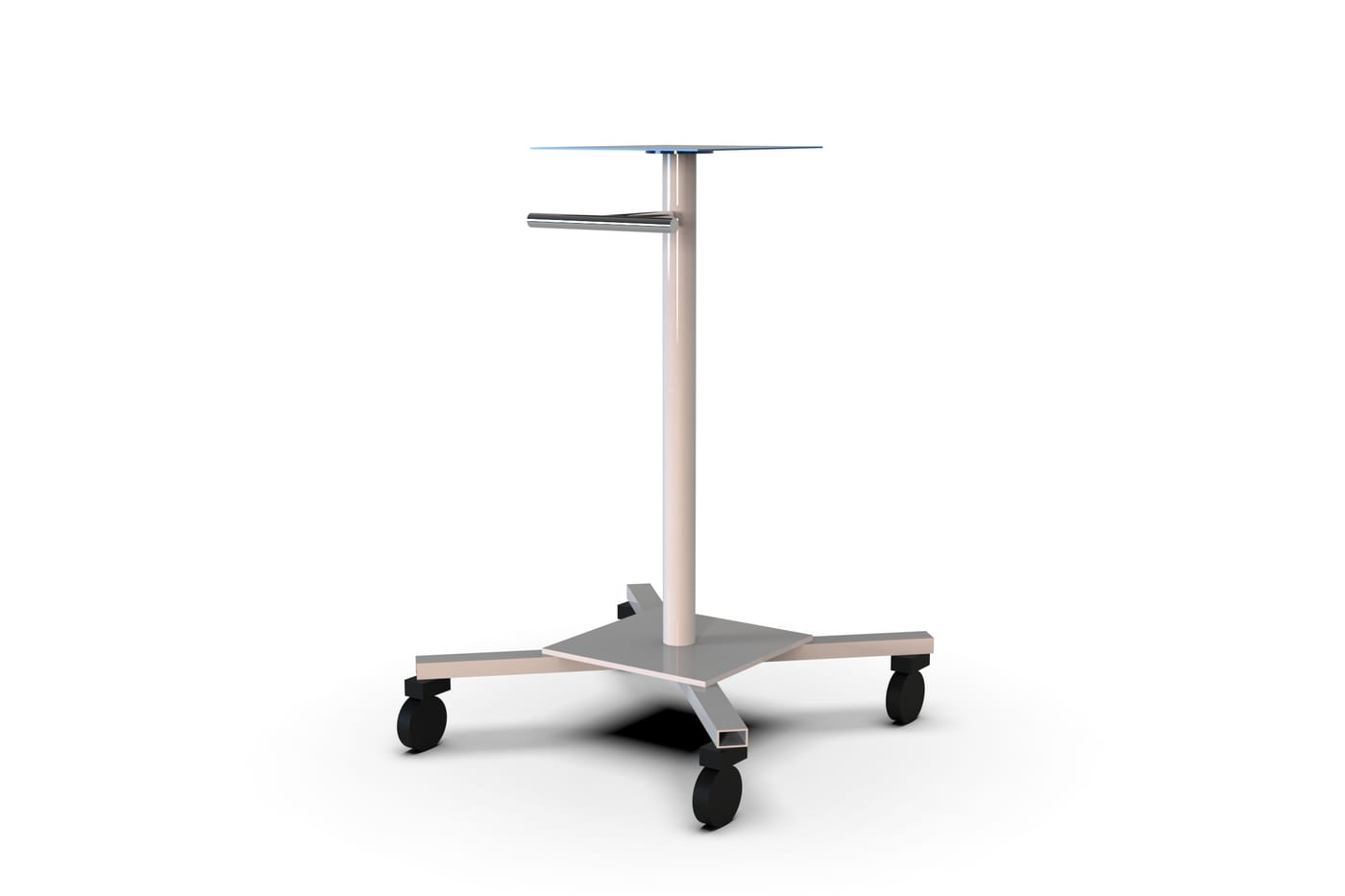
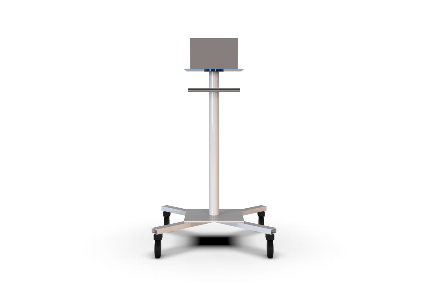
Device cart on swivel castors, 15 kg at 1.07 m
3D CAD in SolidWorks · tipping stability by hand in MATLAB · beam and modal analysis in ANSYS
Cart with column, shelf and handle for a device up to 15 kg. In a tall, light cart the structure is not the problem: tipping is. The first layout tipped with a 70 N push on braked castors, and the design was changed accordingly.
Design data
| Device | up to 15 kg, offset up to 80 mm |
|---|
| Shelf | 400 × 350 mm at 1.07 m |
|---|
| Base | cross, RHS 50 × 30 × 3 |
|---|
| Castors | 4 swivel castors, 100 mm, on a 640 mm square |
|---|
| Ballast | plate 360 × 360 × 10 mm, 10 kg |
|---|
| Column | tube 60 × 3 mm |
|---|
| Handle | 950 mm above floor |
|---|
| Cart mass | 27.8 kg, no interferences |
|---|
| Total mass | 42.8 kg, centre of gravity at 669 mm |
|---|
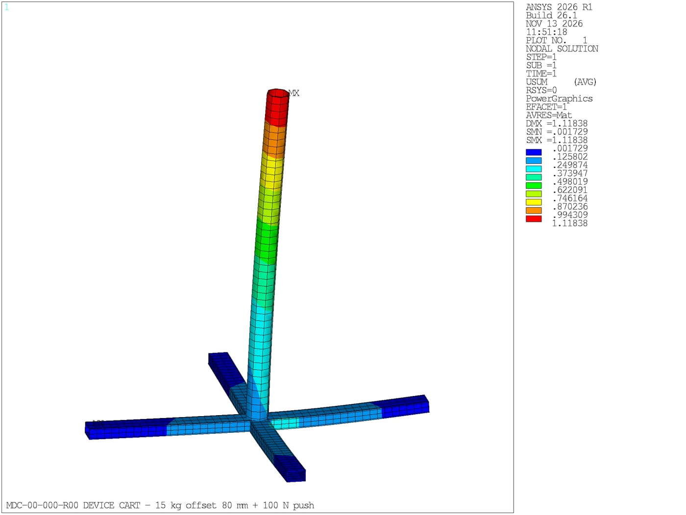
Stability and stiffness
| Tipping angle, worst direction | 20.6° (target 10°) |
|---|
| Push that tips the cart, braked castors | 111 N (target 100 N) |
|---|
| Castor loads with a 100 N push | 29 and 173 N (same values by hand) |
|---|
| Column stress | 13 MPa (hand check 13 MPa) |
|---|
| Shelf displacement with a 100 N push | 1.08 mm (0.57 mm column only) |
|---|
| First natural frequency | 10.4 Hz |
|---|
Method
Stability first: tipping angle and the horizontal push that tips the cart with braked castors, with the device offset and the swivel castors turned the unfavourable way. The first layout, with castors on a 560 mm square and no ballast, tipped at 70 N: the base was widened and a 10 kg plate added. A beam model of 142 elements then gives castor loads, stresses, shelf displacement and natural frequencies.
Limits. The two targets (10° tilt and 100 N push) are criteria chosen for the study, not a verification against a standard: a real product must pass the tests of the applicable standard. The margin on the push is small, 11%. Threshold crossing, real castors and brakes, cables and cleanability are not covered.
Project sheet (PDF)
Waste handling and recycling · SKP-00-000
Self-dumping skip for forklift, 750 L and 1,000 kg
3D CAD in SolidWorks · balance and statics by hand in MATLAB · beam analysis of the frame in ANSYS
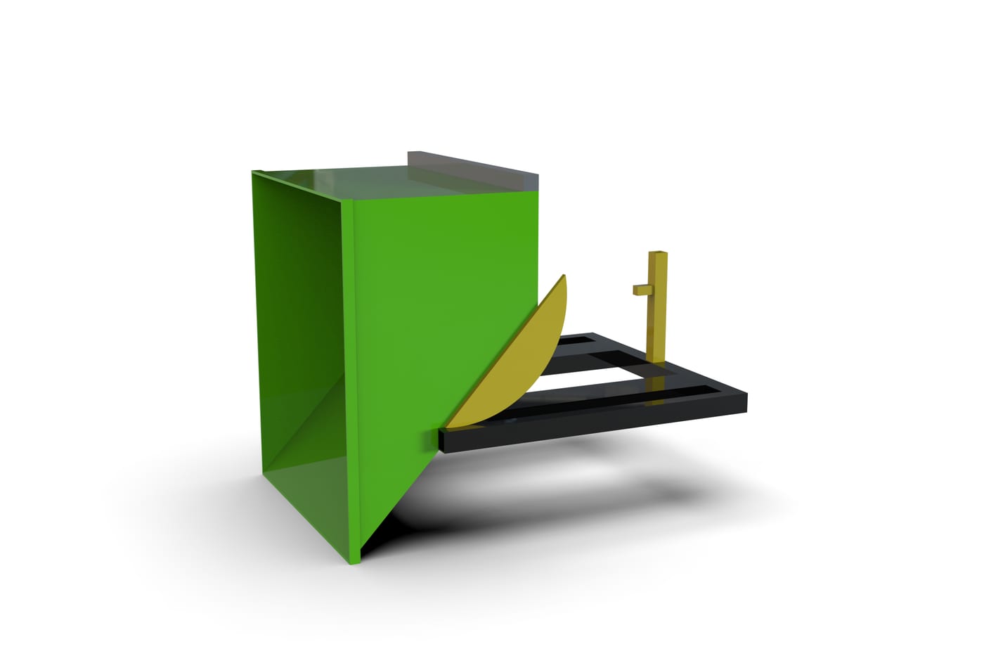
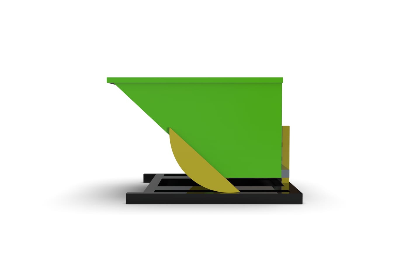
Skip for scrap and waste that empties by rolling forward on two circular rockers. The design is all about balance: when full it must tip by itself once the latch is released, when empty it must return by itself. The first layout tipped by itself only when filled above 93%, and the design was changed accordingly.
Design data
| Capacity | 750 L, 1,000 kg |
|---|
| Body | 1,300 × 1,136 × 750 mm, front wall at 43° |
|---|
| Plates | sides and front wall 3 mm, rear 5 mm, bottom 8 mm |
|---|
| Rockers | circular segments, radius 450 mm, 20 mm plate |
|---|
| Counterweight | bar 60 × 60 mm at the rear, 32 kg |
|---|
| Rails | RHS 60 × 80 × 5 |
|---|
| Fork pockets | RHS 200 × 80 × 5, 700 mm apart |
|---|
| Dumping | 90°, rolling 707 mm forward |
|---|
| Mass | body 199.5 kg, 299 kg in total, no interferences |
|---|
Balance and frame
| Tipping moment at release, full | +852 N·m (2.7 kN on the latch) |
|---|
| Minimum fill to dump by itself | 55% (93% without counterweight) |
|---|
| Return moment when empty, 0 to 90° | 46 to 199 N·m |
|---|
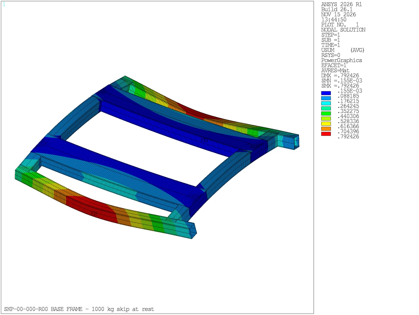
| Fork loads at rest, front and rear | 2.88 and 3.52 kN (by hand 2.86 and 3.51) |
|---|
| Rail stress at rest | 43 MPa (by hand 57 MPa, simply supported) |
|---|
| Rail stress at the end of travel | 21 MPa (by hand 21 MPa) |
|---|
| Rear fork at the end of travel with the load still inside | −0.28 kN: the frame must be held down |
|---|
Method
On flat rails a circular rocker balances like a pendulum about its own centre: the body tips if its centre of gravity is ahead of that centre and returns if it is behind and below. The rocker centre was placed so that the empty body returns by itself from any angle. That way, however, it tipped by itself only above 93% fill: a 32 kg bar at the rear moves the centre of gravity of the empty body and brings the threshold down to 55%. A beam model of the frame with 744 elements, resting on the forks, then gives stresses, deflections and fork loads at rest and at the end of travel.
Limits. The load is taken as level and rigid until release: with uneven filling the threshold changes, and below 55% a push is needed (220 N at 30% of the volume). Rolling without slipping is an assumption: the teeth or chains that ensure it, the end stop, the latch and the retaining chain to the truck are not designed. Welds, body plates, rocker-to-rail contact and the stability of the forklift are not verified. At the end of travel the lip drops 380 mm below the support plane: the skip must be dumped while raised.
Project sheet (PDF)
Do you have a project to develop?
Send us a few lines, a drawing or a sketch: you receive in writing what we deliver and when.
Request a quote